Open
IFC Viewer User
Guide
General Information
Open IFC Viewer is a professional-grade viewer for IFC files developed by Open Design Alliance (ODA). Open IFC Viewer can view and work with new IFC versions and experimental IFC features from bSI (buildingSMART International). Powered by Visualize from ODA, it is optimized for large models.
Download and Install Open IFC Viewer
Open IFC Viewer is available for Microsoft® Windows® and Apple® OS X® platforms.
To download and install Open IFC Viewer:
- Go to openifcviewer
- Click Download
- Save the file to your computer
- Run the downloaded file and follow the instructions
Launch Open IFC Viewer
To start Open IFC Viewer, double-click the Open IFC Viewer desktop shortcut that was created during installation. Or you can launch the OpenIFCViewer.exe executable file (on Windows) that is located in the installation folder.
Open IFC Viewer first displays with an empty drawing area, tab bar, quick bar, and side panels. Many options and actions are not available until you open a file.
Work with Files
Open a File
IFC is the native file format for working with Open IFC Viewer.
To open an IFC file:
- Choose File > Open, click Open on the quick bar or press CTRL + O
- Navigate to a file, choose it, then click Open
A progress bar appears when opening a file. The top bar shows the progress at each stage of opening the file, and the bottom bar shows the overall progress of opening the file.


Open and Validate a File
You can perform validation tasks when opening a file by choosing File > Open and Validate Model
For more information about validation, see the Model Validation section.
Modeler-Related Import Parameters
Open IFC Viewer uses a modeler to work with 3D models and geometry that can be later displayed by a rendering application. The modeler can create new model bodies (for example, boxes, spheres, extrusions, etc.) and can modify existing bodies via Boolean operations. Those bodies can be rendered later by an application. ODA Facet Modeler is the default modeler used by Open IFC Viewer.
Deviation
To visualize a circular shape, for example, a renderer needs to have segments that compose a shape. If a circle is represented by an equation, theoretically it can have an endless number of segments, therefore it needs to be triangulated. The following settings are available:
- Deviation — specifies how much the triangulated shape can deviate from the representation by an equation. Lower values provide more accurate representations of objects after the triangulation at a cost of increased number of segments. Higher values provide more rough representations by using fewer segments. The default value is 0.5
- Min per circle and Max per circle — set bounds for segments during the triangulation. The resulting shape does not have fewer segments than the minimum-per-circle value, and it does not have more segments than the maximum-per-circle value
B-Rep Tolerance
The B-Rep tolerance controls the detail of rendered objects and can be either dynamic or static. This option controls how advanced B-Reps (objects that are drawn as- is, i.e., non-faceted bodies are created for these objects) deviate from original NURBS or analytical surfaces.
Lower tolerance values produce a more visually correct result but increase the load time of a file.
Here are examples of different values for dynamic and static settings:


Export a File
You can export an open file to PDF, HDF5, and ifcXML formats. To export a scene to one of these formats, choose File > Publish PDF, EXPORT to HDF5, or EXPORT to ifcXML.
The next example shows how to export a scene to a PDF file and view it with Adobe® Acrobat® Reader®.
Append a File
To append an existing file to the currently opened file, choose File > Append.
Write to a File
To write changes to an existing file, right-click of the root node displayed in Object Explorer and choose Write in File. The current state of the IFC model can be written to all formats supported by ODA IFC SDK, including IFC, ifcZIP, ifcXML, and ifcHDF5.
Explore Scene Objects
The Object Explorer panel allows you to explore objects of an IFC model. It displays the spatial structure of the currently opened IFC model according to the ODA Common Data Access (CDA) interface. Click an object in Object Explorer to see its corresponding native properties in the Properties panel on the right side.
In addition to clicking a node directly in Object Explorer, you can select a node by GlobalId (GUID) — right-click in Object Explorer and choose Select by GUID. A GUID can be obtained in different ways. In the video below, the Properties panel is used to get the GUID of a node.
Also, you can right-click the Object Explorer panel to get various statistics about:
- Model objects — statistics for objects in the IFC model
- Open time — time spent for various steps that are necessary for loading an IFC file, creating geometry, displaying geometry, etc
- Geometry-related information — information from Visualize SDK about quantitative characteristics of the geometric representation of the model, for example, count of edges, count of faces, number of shells, etc
Additionally, when clicking a root node in Object Explorer, the Properties panel displays general details, including information from the header section and data section, for example, schema, authors, units, etc.
You can work with the Property Set Manager and Quantity Set Manager by right-clicking a node:
- Property set — a set of properties predefined by the IFC format specification (usually defined by name, value, and unit type) that is associated with an object or object type
- Quantity set — a set of multiple quantity occurrences predefined by the IFC format specification. The data type of quantity occurrence values is count, length, area, volume, weight, time, or a combination of quantities. Quantities are defined by name and value and can additionally introduce their description and formula
The Property Set Manager and Quantity Set Manager are available for most nodes. Once in a manager, you can mark a checkbox of a property set or a quantity set, set up the necessary values and append it by clicking Append. Newly appended property and quantity sets can be viewed in the Properties panel of the corresponding node.
Note
Appended property and quantity sets are NOT displayed in the Properties panel if the CDA Cache Properties option is used when you import the model. This option makes all model data available from cache, meaning that it can't be changed because model data is unloaded from memory. Make sure you disable this option when importing your model if you want to use the Property Set Manager or Quantity Set Manager and then view appended items.

For example, to append a new property set and quantity set for an IFCBUILDINGSTOREY and view them in the Properties panel:
You can hide, isolate, and unhide most nodes in Object Explorer. For more details, see the Hide, Isolate, and Unisolate Scene Objects section.
Tree View
A Tree view provides an easy way of navigating an IFC model in a tree-like manner from the specified node inside Object Explorer. Tree views are available for most nodes — right-click a node and choose Tree View.
Once a Tree View window is open, it displays a line from the IFC file that corresponds to the current node. A root node inside a tree view expands and shows its attributes where explicit attributes display in a regular font and inverse attributes display in italic font. These attributes expand and show other attributes or definitions with their attributes that can also expand and show their corresponding attributes, and so on.
Right-click in a Tree View window to choose how to navigate a file:
-
Search — searches for a line of the specified handle
-
Find by isInstanceOf/Find by isKindOf — performs a search inside a model for definitions of a specific instantiable type (isInstanceOf) or a specific type in general (isKindOf, which finds instances of derived types)
-
Find all users — searches for all objects that reference the specified line
-
Find users by role — searches for all objects that reference the specified line from a specific attribute
-
Set as root — sets the specified node as the root node in the current Tree View window
-
Get instance path — gets a path from the specified instance to the root node. The displayed path is copiable
-
Collapse all — collapses lower-level subnodes of attributes for the specified node
-
Open in new window — creates a new Tree View window for the specified node
-
Find by Global ID — finds a node by its global identifier
A Tree view has additional options for specific definitions:
- ifcBlobTexture
- IfcCartesianTransformationOperator2d/IfcCartesianTransformationOperator3d
- ifcClosedShell
- ifcColourRGB
- ifcColourRGBList
- ifcCurveSegment/ifcCurve/IfcPolyLoop
- ifcObjectPlacement
- ifcSegmentedReferenceCurve
- ifcSurfaceStyle
- ifcPlacement/ifcObjectPlacements
- ifcPixelTexture
- IfcProfileDef
Below is an example of using an additional option to visualize a color definition. In this example, corresponding instances are first searched by type and then each found occurrence can be visualized after using the visualize color option:
Or to visualize a surface style:
Or to visualize a polyloop from a CurveDump plugin:
Object Instances
An other way to explore scene objects is by using the Instance Viewer.In Object Explorer, right-click an object and choose Instance Viewer, which shows the selected instance with its entity definition hierarchy as it is defined within the EXPRESS schema, and all assigned attribute values. To get more details about a line item, right-click an entity name in the Instance Viewer and choose Open Design Alliance Documentation or buildingSMART International Documentation.
Highlight Scene Objects
You can highlight items that belong to an entity or highlight an entity itself. This means you can highlight two types of graphical data — entities and geometry. Highlighting can be done in three ways:
- Single-click — left-click directly on an object to highlight it
- First-click + second-click to the left — define a crossing window that crosses all objects to be highlighted. Objects that fit in or cross the area are highlighted
- First-click + second-click to the right — define a regular window that fits all objects to be highlighted. The objects that fit entirely in the area are highlighted
In the second and third case, the first click should not be on an object, otherwise the first case is activated, and the object is selected and highlighted. The simplest way to highlight is to directly click an entity. You can select multiple entities by pressing Ctrl and clicking them. Highlighted objects are selected in the Object Explorer panel.
By default, only entities are selected and, therefore, highlighted. To select and highlight geometry objects (for example shells), right-click the scene, then choose Selection Level > Geometry. The example below illustrates the difference between selection levels when clicking the same area in a model.
The next example shows highlighted entity objects with a crossing window. To make a crossing window, click anywhere in the scene where no object is located, then click again anywhere to the left of the first click.
The other option is to use a regular window for selection and highlighting. This way, the only objects that are highlighted are those that fit entirely in the window. To use this mode, click anywhere in the scene where no object is located, then click again anywhere to the right of the first click.
You can also highlight objects by hovering over them with the mouse. To turn on this feature, right-click the scene and check Highlight while Hover. The highlight color and modes can be customized by choosing File > Options > Appearance.
Hide, Isolate, and Unisolate Scene Objects
You can hide or isolate various graphical objects by selecting items in a viewport or in the Object Explorer panel. After the required objects are selected (and therefore highlighted), right-click and choose Hide or Isolate. To return to the initial state, use the Unisolate command.
The next example demonstrates using the Hide, Isolate, and Unisolate commands:
Scene Lighting
A rendering scene can have default or user-defined light sources. Since IFC files don't contain separate lights, the default lighting is used for rendering. The default lights have an important feature in comparison to standard lights. Default lights rotate together with a camera allowing an object to be illuminated from each side. The lighting direction of the default lights is defined in the eye coordinate system (not World Coordinate System).
In Open IFC Viewer there is a dialog with default lighting parameters. With help of this dialog, it is possible to change lighting parameters. You can find this dialog by clicking Light Settings in Appearance section, like on the following screenshot:

The opened dialog looks the following way:

Lighting Type
Lighting type option determines which type of light will be used for scene lighting. There are four types of lighting: one light, two lights, back light and user defined.
One light
In this case, a single light source is used to illuminate the scene. This can create a simple and focused lighting effect. Result of applying this option:

Two lights
In this case, two lights are used for scene illumination. The model appears with two rays of lights with dark area is reduced. Result of applying this option:

Back light
In this case, scene uses two lights but with a different placement in comparison to the previous case. Result of applying this option:

User-defined
User-defined light type allow you to control direction of light source. Vector for direction has eye coordinate system. There are several examples of how to setup this light. Direction is (0, 0, 1):

In this case, there is XY plane with Z direction extending from a viewer. The light source is behind the model, so let's change direction of light to (0, 0, -1):

One more example of custom light direction (0, -1, 0):

Light Intensity
Light intensity refers to the strength or amount of light produced by a specific light source. Large intensity values produce brighter light on objects in the scene. To set the intensity of the light, change value of Light intensity filed. For example, lighting with Light intensity field set to 0.5:

Light Color
Light sources can emit different colors. This light color participates together with ambient color, object color, material's diffuse and ambient colors in the calculation of the final color. By default, the white color is used. There is an example with yellow light color:

The scene is rendered the following way if light color changes to blue:

Ambient Color
Ambient light color refers to the color of the ambient (background) light in a scene. Ambient light is a type of indirect or global illumination that represents the light that is scattered and reflected from all directions, regardless of the presence or position of light sources. It provides a base level of illumination to all objects in the scene and helps prevent objects from appearing completely dark in areas where there is no direct light. To illustrate mentioned above, green color is chosen as an ambient color for the first of the previous samples (with yellow light color). The global ambient light is scaled by material's ambient property, which is orange in current case. This provides the following visual result.
This result illustrates the idea of such ambient color: allows to prevent objects from appearing completely dark in areas where there is no direct light. The area which was black in the in case without ambient light starts to have green light.

Display Spaces
By default, Open Ifc Viewer does not import information about spaces into the scene. You can enable displaying spaces with Options > Import > IFC settings > Draw spaces. After importing a file with this option, you can see that spaces now appear in the Object Explorer. Now you can select them, access their properties, hide, isolate, etc.
Available Tools
View tab
The View tab has the following options:

Navigation Group
The Navigation group provides tools that allow you to perform different operations with the camera, for example: pan, orbit, free orbit, and rotation of a view. Example of using tools from the Navigation group:
Camera Group
The Camera group provides tools that allow you to zoom to a window, zoom to extents (or press Ctrl + Backspace), set the projection of a camera, and get a snapshot of the active view. Example of using tools from the Camera group:
Also, you can make a snapshot of a current view with the Make Snapshot tool. Note that additional application elements such as WCS display, view cube, markups, FPS counter, etc. are saved in a snapshot.
Regen Group
The Regen group provides a tool that regenerates geometry data in the scene. Regeneration is a process that recalculates geometry for proper display on the screen. Regeneration can help save resources by reducing object detail when zoomed out in the current view when fewer details are needed. Likewise, regeneration can increase geometry detail after you zoom in to an object and if you see jagged edges. Regeneration is most relevant for curve, alignment, and boundary representation objects. To regenerate geometry, click the Regen tool or press F5. Example of regenerating geometry:
View Group
The View group has several predefined orthographic and isometric views for the camera and the ability to change the viewport configuration to single, two, or four viewports with different layouts. You can also make a viewport active and perform different operations in this viewport. Example of using tools from the View group:
Render Mode Group
The Render Mode group allows you to change the current visual style, for example to sketchy or hidden line. Examples of different visual styles:
Tools Tab
The Tools tab has the following options:

Markups Group
The Markups group provides tools for marking parts of a drawing, for example, render defects, building defects, collisions, key parts, etc. You can create markups from different shapes, free-hand sketches, and text notes, and you can save and load markups.
Note that markups are deleted when orbiting or rotating with the camera. To save a current view with markups, use the Save tool. Then you can load the view with all the markups when needed. Here is an example of how to use markups, save a view with markups, and load the saved view:
Additionally, a work plane for markups can be modified. There are 3 options to set a work plane:
-
Default — sets a default work plane. In this case, center of coordinate system is a center of current view, and the plane is aligned with current viewing plane.
-
Set plane by normal to point — sets a work plane by specifying a normal to a point. In this case, you need to specify a point on surface. The normal is calculated automatically, however, it can be modified manually. The video below shows usage of markups with a plane that is set by this method. Note that for some markups it is important to have a correct up-vector orientation, for example, for text markups. The pop-up dialog also provides an ability to specify the up-vector
-
Set plane by three point — sets a work plane by specifying three points on a surface. In this case, you need to specify the first point that is the start of the coordinate system, the second point that indicates positive X axis, and the third point that indicates positive Y axis. This mode also allows you to manually specify up vector of the work plane if necessary
Note
Markups are saved in snapshots that can be created by choosing View > Make Snapshots.
For more information, see Camera Group.
Measurement Group
The Measurement group contains tools for measuring distances. Distances can be measured between arbitrary points of a model's geometry or between points that strictly snap to vertices of a model. The measurement options allow you to select the color of visual elements used for measurements, snap point size, and measurement units. You can conduct multiple measurements with the same distance measurement type (arbitrary or snapping to vertices). Example of using measurement tools:
Note
While using the measurement tool, all basic camera management options are available via using the mouse wheel. For instance, to move a camera, hold down mouse wheel and move a mouse, or to rotate a camera - hold down Shift + mouse wheel and move a mouse.
As for angles, there are 2 options for measurements:
- Measuring angles specified by 3 vertices on a geometry object
- Measuring angles between plane
In the first case, choose Angle Vertex and specify 3 vertices that lie on a geometry object.
In the second case, choose Angle Plane and specify 2 vertices on different planes to determine angle between those planes. You can also choose points on the same plane but the angle in this case is 0 degrees.
Sectioning Group
The Sectioning group contains tools for working with cutting planes, which are planes that visually cut the geometry of a model. You can show or hide cutting planes, add a cutting plane using the x-, y-, or z-axis, and clear cutting planes. With the Fill tool you can enable or disable a section fill and also specify a fill color and pattern. Cutting planes can be repositioned around the scene. To move or rotate a cutting plane, click it, and drag the highlighted tools.
Collisions Group
The Collisions group contains two collision detection tools. The Collide tool detects collisions between geometric objects and entities in real time. The Collision Detection tool shows all collisions between selected objects. For example, you can use collision detection to check whether geometric objects are aligned properly and do not intersect each other.
To interactively detect collisions:
- Click the Collide tool
- Click an entity to define the input set. Press Ctrl while clicking to select multiple entities
- Press Enter. The input set is collided with all other model objects
- Check the selected objects for collisions with other objects. Drag the coordinate system handles by the x-, y-, and z-axes to detect collisions. Collided objects are highlighted
- When done, press Esc
To show all collisions between selected objects:
- Click the Collision Detection tool
- In the Collisions panel, specify the collision options: type, tolerance, distance, and choose objects for detecting collisions or all collisions
- Collisions are displayed in the Collision Results list. Double-click any item in the list to render a corresponding collision in the scene
- (Optional) Save selected collisions or all detected collisions to the BCF format (.bcfzip file)
- When done, click Close
Note
Collision detection does not apply to helper objects that are not part of the model (annotations, text, dimension objects, referencet objects, etc.).
Explode Group
The Explode group contains a tool for simulating an explosion of all geometry components of a model. When working with the Explode tool, use the slider to control how much the model's elements are scattered as a result of the explosion.
Appearance Tab
The Appearance tab has the following options:

Appearance Group
The Appearance group allows you to turn on or off the display of World Coordinate System (WCS) axes, change light settings, and change the background color to custom or default gradient. Example of using tools from the Appearance group:
Visual Effects Group
The Visual Effects group allows you to enable anti-aliasing for smoother graphics display and to cast a ground shadow under the model. Example of enabling and disabling the anti-aliasing and ground shadow effects:
Panels Group
The Panels group allows you to show or hide the Object Explorer and Properties panels. Example of hiding and showing the Object Explorer and Properties panels:
Plugins Tab
The Plugins tab has the following options:

Animation Plugin
The Animation plugin provides an ability to animate camera movement along a curve. The plugin works with instances of IfcAlignment type. Plugin's features:
- Reverse traveling path
- Setup custom animation duration time
- Setup approximative epsilon in range [0..1]
- Setup Frames Per Second (FPS) of the animation
- Setup one of the interpolation methods for keyframes of the animation
- Setup camera offset from the path by X and Z axes
- Setup custom number of frames forward for the camera (i.e. camera reacts to the path's curves several frames earlier before the distance is travelled)
- Lock a camera orientation to either a direction vector or point in 3D space.
Once animation with appropriate parameters is generated, you can play it, reset it, run through it by dragging or navigate it frame by frame.
Note
Create an animation for multiple curves by pressing Ctrl while selecting multiple IfcAlignment objects and then starting the Animation Plugin tool.
BCF Manager

The BCF Manager is a plugin that allows you to work with BIM Collaboration Format (BCF) files, which allow you to communicate various model-related issues with other BIM applications through materials that were previously shared among project participants. This can be achieved by performing a file exchange between software platforms or using a service to connect these software platforms. BCF is a buildingSMART International open standard.
With the BCF Manager plugin, you can create a new project or open an existing one. BCF projects are stored in files with the .bcfzip extension. Once a project file is created or opened, a panel displays options for managing a project.
A BFC project consists of topics that can be added via the panel. Example of creating a new project and adding a topic:
For each topic you can add a comment describing an issue. A comment can be viewed in the Details section along with other information describing a topic.
Each topic can have multiple viewpoints. Each viewpoint has its index that specifies the position of a viewpoint in a list. You can switch between viewpoints by clicking Previous and Next. A viewpoint can be formed as:
- Free selection — the current viewpoint shows the whole model and its selected (highlighted) parts
- Selection highlight — the current viewpoint shows only the selected (highlighted) parts of a model. The parts of the model that are shown are isolated, i.e., the rest of the model is hidden
- Intersection search — the current viewpoint shows only the selected parts of a model that are highlighted in one color; other parts of the model that intersect with the selected parts display in another color. The parts of the model that are shown are isolated, i.e., the rest of the model is hidden
Free selection:
Selection highlight:
Intersection search:
When all necessary topics with viewpoints and other information are created, save the current BCF project to a .bcfzip file which can later be opened by Open IFC Viewer with the same BCF Manager or opened by other software.
COBie Manager
Construction Operations Building Information Exchange (COBie) is a non-proprietary data format relating to managed asset information. COBie helps to electronically capture and record various project data at the point of origin. COBie primarily contains data about the objects within a model including equipment lists, product data sheets, warranties, etc.
The COBie Manager plugin launches a window with a spreadsheet containing tables with information about:
- Contacts
- Components
- Jobs
- Facilities
- Systems
- Impacts
- Floors
- Assemblies
- Documents
- Spaces
- Connections
- Attributes
- Zones
- Resources
- Coordinates
- Types
- Spares
- Issues
Click the COBie Manager icon in the Plugins tab to launch the manager. Once the manager is launched, you can view various model-related information in the created tables. In addition to the information from list above the table contains the Instructions tab that contains general information and data labeling helpers that explain what colors mean in other tables.
Model Validation
The Model Validation plugin checks that the model meets requirements for the exchange of BIM data. The validation uses the Information Delivery Specification (IDS) standard by buildingSMART to satisfy SDAI or IFC validations, checking whether a file is correctly composed from the perspective of IFC and DAI or to meet user-defined requirements for IFC models. When starting the Model Validation plugin, a warning displays instructing you to set up an IDS folder in the application settings (Options > Plugins > Model Validation). This step is necessary if you plan to use user-defined validations from IDS or XML files. If such validations are not required, omit this step.
When the required validations are chosen, click Validate to launch the validation tool. When the process is finished, a new dialog displays the validation results, which can be filtered and saved in text or HTML format.
Also, it is possible to perform validation when opening files by choosing File > Open and Validate Model.
When performing validation on file loading, it is possible to try to heal some of the validations that failed to set up. Note that healing works only for known validation cases, so it is not guaranteed to work every time.
Layers Manager Plugin
The Layers Manager plugin allows you to view and manage properties of existing layers. Available layer properties that can be changed:
- Name
- Visibility
- Color
- Line type
- Line weight
- Description
- Identifier
By default, Layer Manager manipulates Visualization model layers data, such changes aren't applied to the original IFC Model. Apply to IFC Model button applies performed changes to IFC model, so all such applied changes appear within IFC file if perform Right click on node in Object Explorer/File Write.
Below you can see a layer manager that displays layers and their properties.

After changing visibility of the first layer:

Customize Viewer Options
Choose File > Options to configure Open IFC Viewer according to your needs.
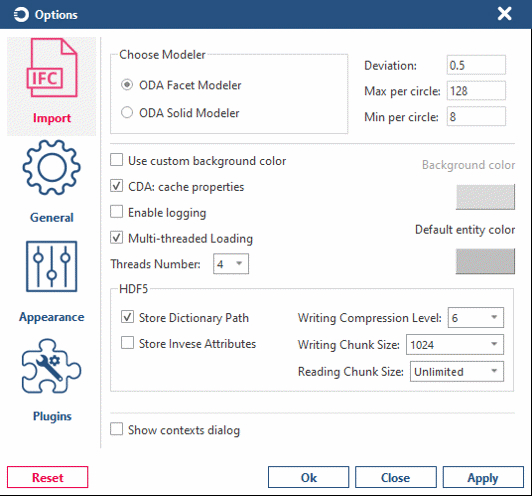
-
Import options allow you to specify the modeler, multi-threaded loading, scene graph, selectability, and other options that are used during import
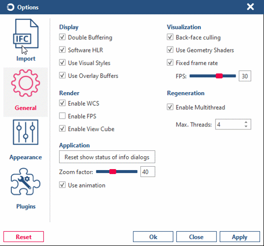
-
General options allow you to set up the device, visualization, render, regeneration, and other general application options
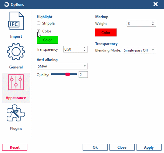
-
Appearance options are used to set up highlight, markup, anti-aliasing, and transparency options
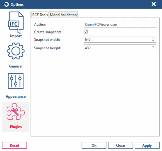
-
Plugin options are used to set up BCF and model validation options


About Open IFC Viewer
Choose File > About to get information about the current Open IFC Viewer application, including the current version, supported schemas, contacts, links, and other information.
